Avoiding and correcting sample-induced spherical aberration artifacts in 3D fluorescence microscopy
Published in Protocols & Methods
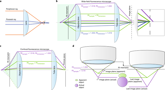
Refraction occurs when light crosses an interface between materials with different refractive indices (RI), which describes the speed at which light travels in a material. Light bends, or refracts, according to Snell’s Law, which defines the angle of bending according to the angle of incidence and the degree of RI mismatch.
Tissue Clearing methods have popularized and streamlined the practice of equalizing the RI throughout a biological sample, which is typically a mess of membranes (RI = 1.46), water (RI = 1.33) and proteins (RI > 1.50), to limit the incoherent scattering of light (explored here by the same authors). However, the light path of a microscope continues beyond the sample, providing ample opportunity for further refraction. Specifically, our recent publication focuses on the small gap between the sample and the objective lens and what care should be taken to match the RI of your sample to the RI of the material filling this gap. Commonly, this gap is filled with air, and the sample itself is protected by a thin sheet of cover glass. In experiments where resolution is maximized, a drop of immersion oil is added between the glass coverslip and an appropriate oil immersion lens. Why oil? The oil itself has a matched refractive index to glass, so that light leaving the cover glass will continue in the same direction rather than bending outward, thereby missing the objective lens. The resolution of the final image as well as its brightness depends on collecting as many of these rays as possible, especially the ones at high angles from the normal. Likewise, when rays enter the sample at different angles (for example, in a point scanning confocal microscope focusing an excitation beam into a sample), these rays are bent at the site of RI mismatch. They bend to varying degrees due to their different incident angles (Snell’s Law), and therefore no longer focus to a point. This is called spherical aberration and reduces both resolution and brightness.
In our paper, we highlight that to minimize spherical aberration, the sample RI must be well matched to the RI of the immersion medium. For example, high RI mounting media (RI ~1.52) match the RI of the cover glass and immersion oil. Other common mounting media for fluorescence microscopy are often glycerol-based and have varied RIs. These are well matched to glycerol immersion objectives while live samples are best imaged with water or silicone oil objectives. Tissue clearing, mentioned above, has introduced a wider variety of mounting media, including glycerol, Dibenzyl ether and Ethyl Cinnamate. Because cleared samples are frequently quite large, many researchers opt for long working distance air objectives to image through these samples. It should be noted, however, that this introduces a large RI mismatch between the air (RI = 1.00) and the high RI clearing media (DBE RI = 1.56) and therefore substantial spherical aberration. Therefore, best practice is to choose an objective optimized for a sample’s particular RI whenever possible.
Unfortunately, a perfect match is not always possible, and the problem is further complicated by appreciating how spherical aberration can alter the Z dimension of a thick sample and confound volumetric measurements. Because converging rays are aberrated by an RI mismatch (for example, low RI immersion medium to high RI mounting medium), the approximate point to which they focus is deeper than expected and the optical “Z-step” is therefore larger than the physical movement of the objective or stage. This produces an axial distortion in the final image (see image below). Have you ever created a 3D rendering of your sample and thought it looked a little too much like a pancake? Or complained that your mounting medium is shrinking your sample? This could be due to spherical aberration. Unfortunately, lost axial information cannot be recovered post hoc by correcting optical section spacing in the final image. The best practice is to calculate the proper sampling frequency prior to acquisition based on the known RI mismatch present in the system (if RI mismatch itself cannot be eliminated). In our article, we summarize previous computational methods to calculate appropriate sampling in the event of RI mismatch and present an efficient compromise. We package this correction in a FIJI macro, which can be used prior to imaging to calculate appropriate sampling or after imaging to adjust z-spacing.
Microscopists, at the very least, should explore the refractive index of materials they are using and the objective lenses available to them; the cure to a dim or blurry image may be a simple tweak away.
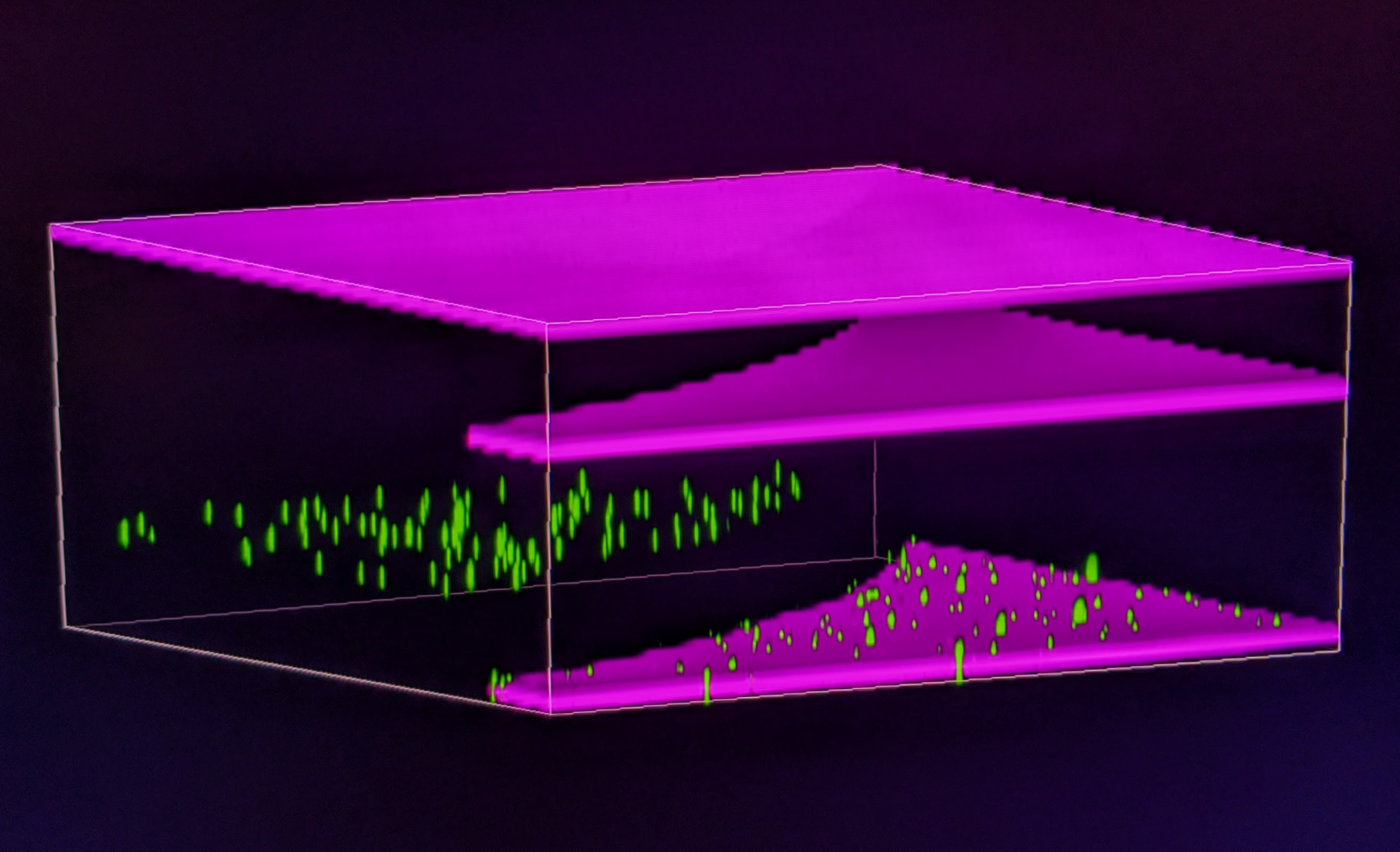
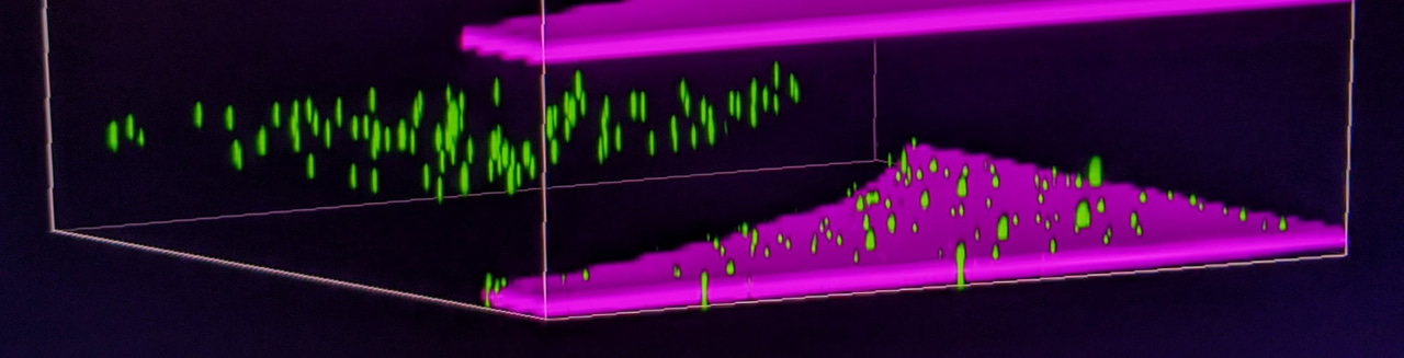
Fluorescent beads dried to a glass slide and imaged with an air objective appear to float upward within a droplet of oil with high RI. In magenta, the excitation light is reflected at interfaces of RI mismatch: (from bottom to top) top of glass slide to air (between slide and cover slip), air to bottom of cover glass, and top of cover glass to air (between cover slip and objective). Two of these reflections are missing within the oil droplet because there is minimal RI mismatch between the oil and glass. In green, the fluorescent beads appear at two different planes despite being, in reality, against the surface of the glass slide (bottom most magenta plane). The RI mismatch between the oil droplet and the air between the objective and cover glass creates this spherically aberrated shift in apparent sample location.
Follow the Topic
-
Nature Protocols

This journal publishes secondary research articles and covers new techniques and technologies, as well as established methods, used in all fields of the biological, chemical and clinical sciences.


Please sign in or register for FREE
If you are a registered user on Research Communities by Springer Nature, please sign in