Topological domain wall induced by atomic intercalation in graphene
Published in Materials

Why we focused on atomic intercalation
In van der Waals (vdWs) materials, the physical properties deeply relate to the stacking structure of layers. For instance, unconventional superconductivity appears in twisted bilayer graphene [1], and topologically protected helical edge states emerge between different stacking domains of bilayer graphene [2]. Mechanical exfoliation has been used to control the stacking structures, which can realize the stacked vdWs layers with arbitrary stacking angles. However, such a way has limitations preventing applications because of the relatively small sample size (< ~100 μm) and difficulty in the mechanical operation. Atomic intercalation into the vdWs layers, on the other hand, is also a widely known technique to modulate the properties of vdWs. The stacking structures such as AA, AB, and BA can be changed by the atomic intercalation because of altering the stability of stacking structures. The intercalation method has no limitation for the sample size, and the degree of intercalation/deintercalation can be controlled by an electric field as seen in a graphite electrode used in Li-ion battery. However, there have been no direct dynamic structural observations as intercalants actually enter graphene layers during intercalation.
Experimental method and system
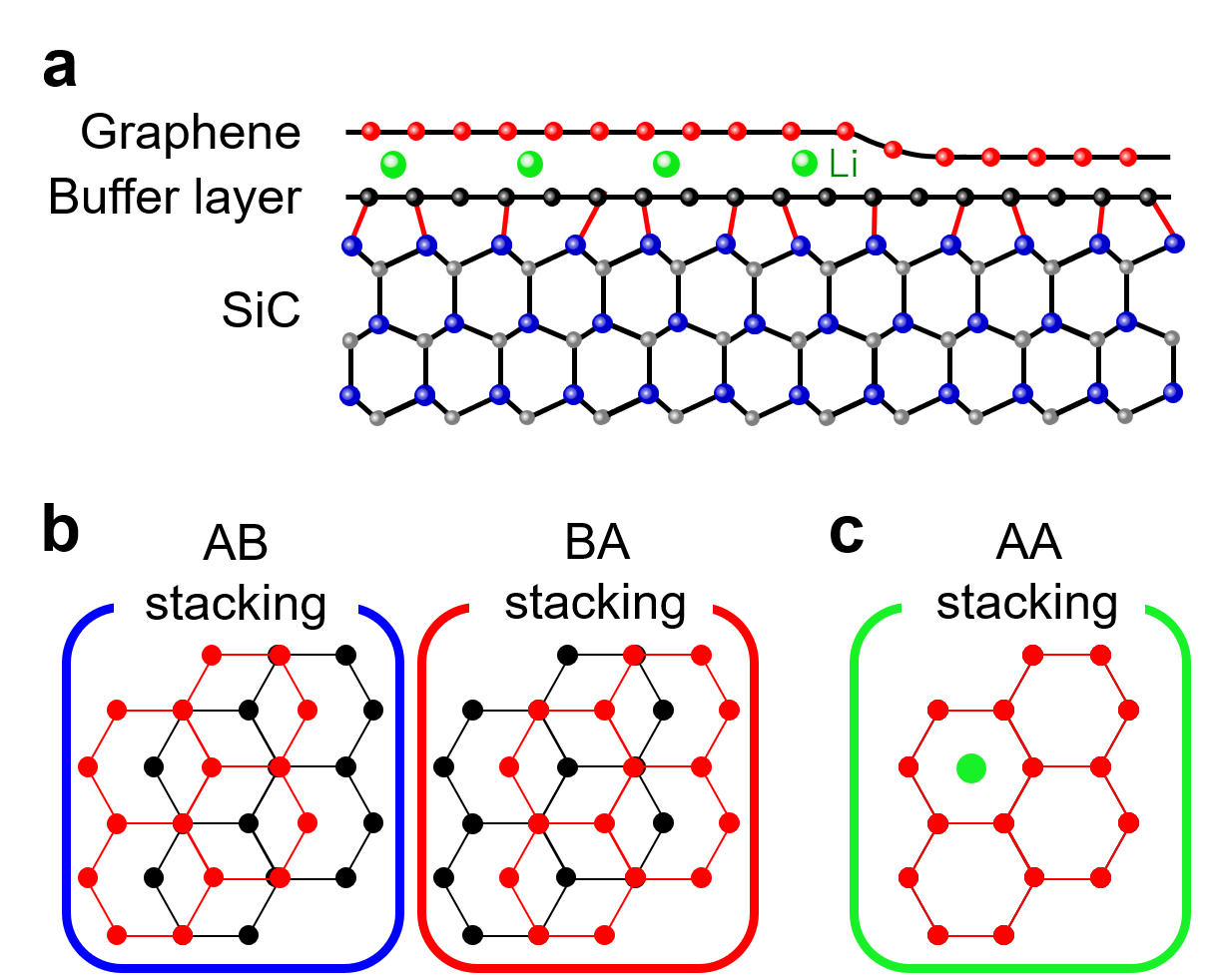
We have applied in situ ultrahigh-vacuum (UHV) aberration-corrected low-energy electron microscopy (LEEM) to direct imaging of the Li-intercalation process into epitaxial graphene (EG) on a SiC (0001) substrate in real-time with nanometer resolution. EG on SiC usually has the buffer layer which is an insulating carbon monolayer depicted as black balls in Fig. 1(a). The buffer layer and the top graphene layer form a carbon bilayer configuration (named as bilayer system thereafter). AB and BA stackings (Fig. 1(b)) are the most stable stacking structures for a pristine bilayer system, but with Li-intercalation the stable stacking structure changes to AA as shown in Fig. 1(c) [3]. We deposited Li on the bilayer system with a low flux rate to capture the Li-intercalation dynamics.

Fig. 1 Stacking structures and Li-intercalated interlayer. a Cross-section image of Li-intercalation into graphene-buffer interlayer. b, c AB, BA, and AA stacking structures.
What we observed
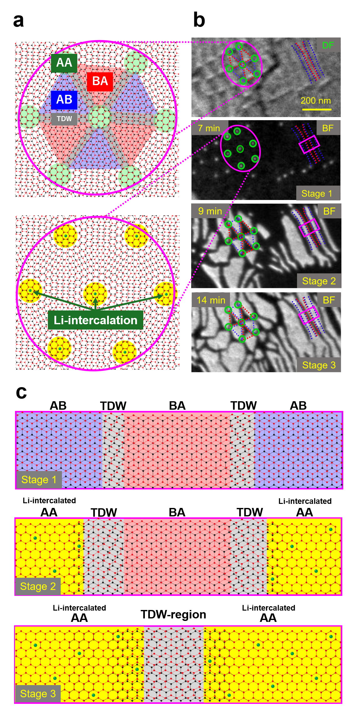
The top illustration of Fig. 2(a) shows the stacking distribution of the pristine bilayer system. AB and BA stacking domains are alternately distributed sandwiching topological domain walls (TDWs) in between. The TDWs are topologically protected due to the different number of unit cells in the buffer and graphene layers, which is different from conventional out-of-phase counterparts. The crossing points of multiple TDWs are called topological crossing points (TCPs), featuring a topologically protected AA stacking structure [4]. The top of Fig. 2(b) is a dark-field LEEM image of the pristine bilayer system. The dark and bright domains correspond to AB and BA stacking domains, respectively. They are consistent with the top illustration of Fig. 2(a). Subsequent Li-intercalation changes the contrast of the bright-field LEEM image. At 7 min of the Li-intercalation process (Stage 1 in Fig. 2(b)), regular bright dots appear at the same positions of TCPs, as illustrated in the bottom illustration of Fig. 2(a). This indicates the start of Li intercalation at each AA stacking domain. At 9 min of the Li-intercalation process (Stage 2 in Fig. 2(b)), the Li-intercalated domains with bright contrast grow spread from the dots of TCPs to the regions which were AB stacking domains (surrounded by or between blue dashed lines in Fig 2(b)) in the pristine state. Further Li-intercalation makes the Li-intercalated domains extend into the regions of BA stacking domains (surrounded by or between red dashed lines in Fig 2(b)) as shown in Stage 3 of Fig. 2(b). Finally, the Li-intercalated domains fill the whole region, but they do not combine with each other and are divided by dark lines (i.e. TDW regions).
How we understood
To get at the mechanism of the stacking-dependent Li-intercalation, we performed density functional theory calculations. The magnitude of Li adsorption energy into AA, AB, and BA stackings is in the order of AA < AB < BA. Thus, it is energetically preferable for Li to intercalate the AA points (TCPs) first and then selectively intercalate AB domains instead of BA domains, which is consistent with the LEEM snapshots. In addition, we calculated the stable stacking structure of the Li-intercalated bilayer system with a Li-concentration corresponding to the experiment. As a result, we figured out that the Li-intercalated domains have an AA stacking structure.
Next, let us focus on the dynamics of stackings in the stripe microstructure as seen in the pink rectangle regions in LEEM snapshots (Fig. 2(b)), with molecular dynamics simulation. As shown in Stage 1 of Fig. 2(c), AB and BA stacking domains are divided by a TDW before Li-intercalation. With Li-intercalated domains growing, AB stacking changes to AA stacking (Stage 2 in Fig. 2(c)). Then, further Li-intercalation proceeds, and BA stacking also starts to change to AA stacking. As seen in Stage 3 of Fig. 2(c), finally, Li-intercalated domains with AA stacking fill the whole region except for TDW regions. Li-ion is not able to stay in the TDW region which can not be AA stacking due to the topological protection. Thus, the TDW region acts as the domain boundary of Li-intercalated domains.

Fig. 2 Dynamics of stacking structures during Li-intercalation. a Schematic pictures of stacking distributions in the pristine state and the Li-intercalated state around TCPs (initial AA stacking regions). b Top image: Dark-field LEEM image showing the initial stacking domain structures (pristine state). Stage 1-3: Bright-field LEEM snapshots during Li-intercalation, the intercalated domains have bright contrast. c Schematic pictures of the stacking structures for Stage 1-3 in the pink rectangle region in (b).
Summary
The highlights in our work mainly include: (i) Li-intercalation into the bilayer system proceeds following the initial stacking structure from AA, AB, to BA regions. (ii) Li-intercalated domains are separated by nonvolatile TDW regions because of the topological protection.
The stacking-dependent intercalation and the dynamic evolution of TDWs are key phenomena for realizing the wafer-scale, controllable stacking engineering for vdWs layered materials not just for graphene. Since TDW is a wall that does not disappear regardless of Li intercalation status, it could be regarded like a magnetic wall and applied to a novel memory device. Furthermore, we expect our findings to contribute to understanding the atomic scale mechanism of Li intercalation and the electric charging in graphite battery electrodes.
For more details, please check out our paper “Dynamic topological domain walls driven by lithium intercalation in graphene” in Nature Nanotechnology.
References
[1] Cao, Y. et al. Unconventional superconductivity in magic-angle graphene superlattices, Nature, 556, 43-50 (2018).
[2] Ju, L. et al. Topological valley transport at bilayer graphene domain walls. Nature 520, 650-655 (2015).
[3] Caffrey, N. M. et al. Structural and electronic properties of Li-intercalated graphene on SiC(0001). Phys.Rev. B 93, 195421 (2016).
[4] Alden, J. S. et al. Strain solitons and topological defects in bilayer graphene. Proc. Natl. Acad. Sci. USA 110, 11256-11260 (2013).
Follow the Topic
-
Nature Nanotechnology

An interdisciplinary journal that publishes papers of the highest quality and significance in all areas of nanoscience and nanotechnology.


Please sign in or register for FREE
If you are a registered user on Research Communities by Springer Nature, please sign in