Ultrafast small-scale soft electromagnetic robots
Published in Electrical & Electronic Engineering

Just like the Olympics with its slogan “Faster, Higher, Stronger”, we are similarly eager to see faster and better performing robots. Our previous work1 has demonstrated that soft electromagnetic actuators (SEMAs) based on liquid metal channels and elastomer shells can be super-fast. With this in mind, we have been thinking on how to use this technology for designing a high-speed soft electromagnetic robot (SEMR). Surely, this would pose an interesting challenge. Here we would like to share some stories about the making of our latest paper.
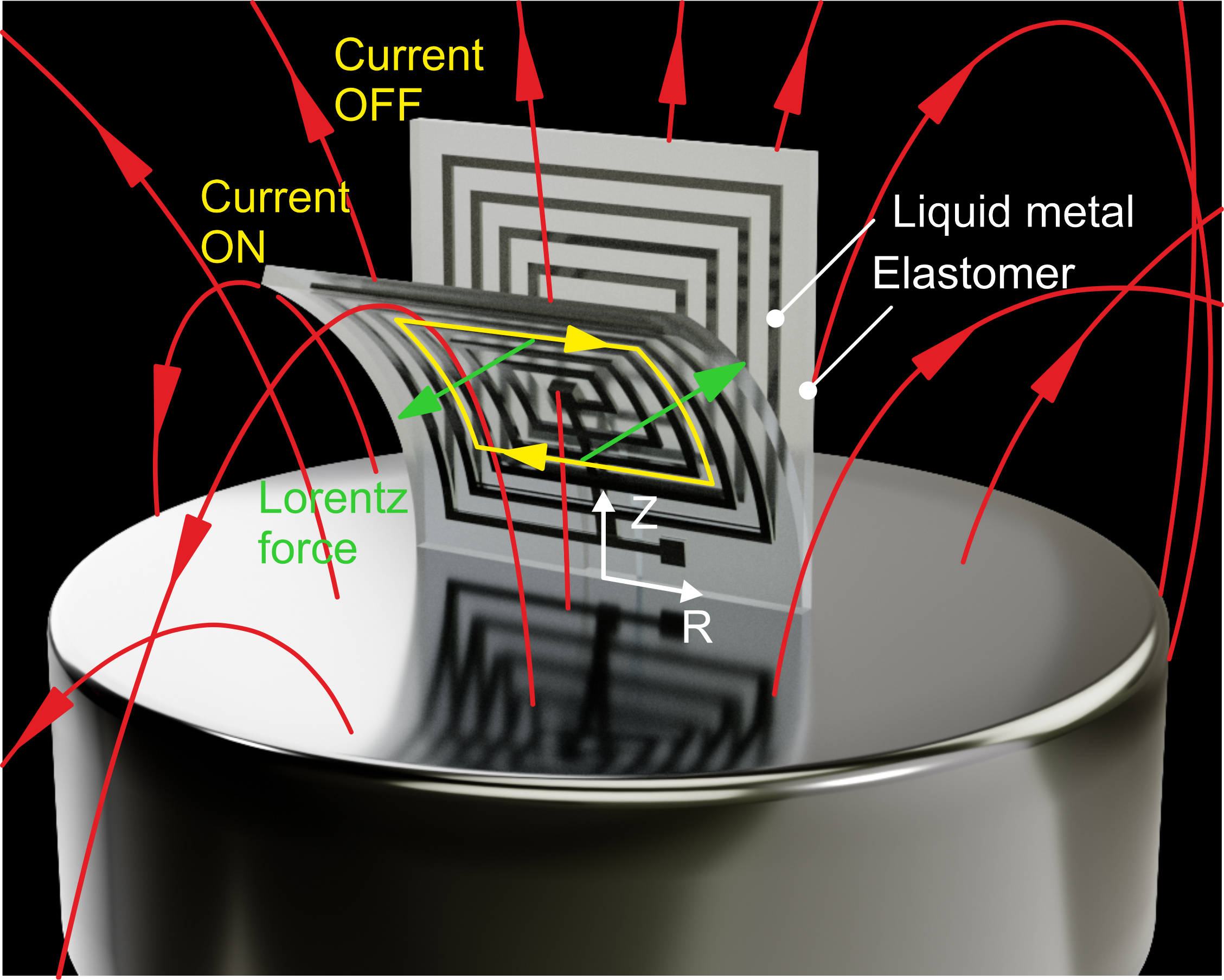
1. Design and fabrication of the robot body
In our previous work1, we have shown that a square SEMA can bend itself, see Figure 1. The simple way to produce a robot capable of running is to combine two such actuators into a V-shape (Figure 2). When activating the robot, the V-shape SEMR closes and opens its two legs similar to a running cheetah. It is also known from our previous work1 that a smaller robot requires less driving current. Therefore we set the aim to develop a millimeter-sized robot. In our previous paper, we used a modeling method to fabricate a few 4-cm actuators. However, this method is not suitable for millimeter-sized robots (we know many groups are able to accomplish this with microfluidics). We decided to use 3D printing technology, which is very flexible and there are a lot of pioneering references, for example a paper from Michael Dickey’s group2. Even with so much pre-existing work, it still cost us about six months to build a stable liquid metal 3D printer. Multiple design iterations were required, because we used an affordable commercial FDM printer as our base. A lot of effort went into increasing the stability of the printing platform. Our liquid metal 3D printer can only print two-dimensional, flat patterns. How could we build a V-shape robot with this? The answer lies in a bilayer manufacturing technique. We printed the liquid metal traces on a stretched membrane, which is bonded to a frame, and then we cover the liquid metal with elastomer. When released, this bilayer film starts to curve due to a strain mismatch between the two layers. We built a simple theoretical model and a numerical tool to predict the curvature of the bilayer membrane in order to get an almost perfect 180-degree half-circle shape (Figure 3).
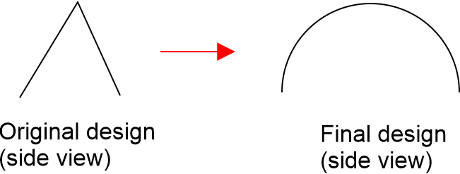
Figure 2. Schematic side view of the SEMR designs. More details can be found in the paper.
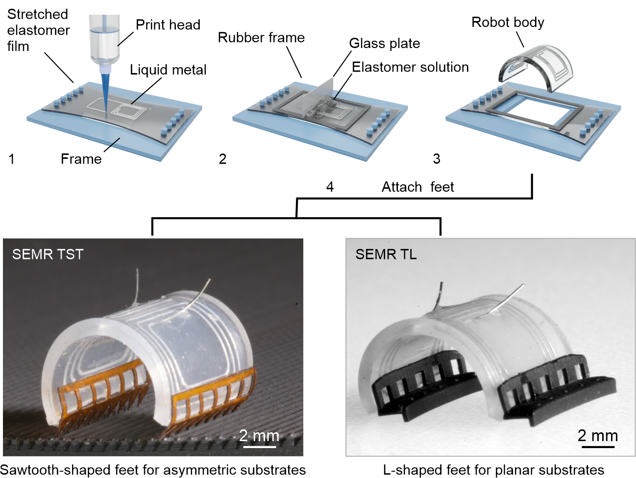
2. Feet design
The more challenging design were the feet. We tried and gave up on many straightforward methods, because the small scale of the robot was problematic. One example was using hooks as the feet of the robot. There are several reasons for that. First, most hooks or needles are made of steel, which is attracted by a magnet. Second, it is difficult to attach a hook or a needle to the robot due to the small size (9 mm body length, 1 mm body thickness). Third, even after having successfully attached needles/hooks, the SEMR could not run properly. Eventually we considered a foot made out of a thin film. This would be a convenient choice, because it’s easy to assemble. Luckily, we have a roll of Kapton film in the lab. We can easily obtain the desired shape with a laser cutter. Unfortunately the Kapton feet do not work on flat surfaces and require a special substrate. Even so, it is a good design to test the maximum ultimate speeds in optimal conditions. Still, a more universal feet design was necessary. There are a lot of papers talking about the role of friction in the locomotion of animals, such as the work about geckos3. We tried to print structures similar to a gecko’s feet with a stereolithography (SLA) printer (Figure 4). We succeeded to print small feet, but they were not working as intended. Luckily, we observed that one version worked in a different way and managed to optimize the geometry to arrive at the final version (Figure 4).
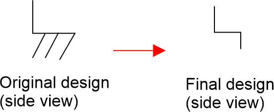
3. Magnet
It is clear that a stronger magnetic field induces a higher Lorenz force and therefore better performance of the SEMR. This is especially important for the untethered version due to the weight of the battery and controller. At that moment, we already had a strong plate magnet (100 mm x Ø30 mm), but we managed to find an even stronger one with a size of 120 mm x Ø50 mm, making it one of the largest permanent magnets available on the market. Our idea was to order two and then stack them. It is quite tricky to combine two strong magnets safely, as shown in this YouTube video “Monster magnet meets monster magnet...”. Rather than building complex equipment, we simply placed a lot of wood plates between the two magnets and slowly removed them one by one.
4. PCB design and battery selection
The PCB design for the untethered robots proved to be an interesting engineering task. The prime objective was to keep the weight and overall dimensions minimal, whilst still providing sufficient functionality. In the case of the walking robots this resulted in a simple and compact board based around the classic 555 timer driving a transistor. In a way this represents the minimum viable circuit for the task. We had more leeway with the swimming robot, due to the buoyancy provided by the styrofoam allowing for a heavier robot. This enabled features such as polarity switching, current regulation and short circuit protection. One obstacle was the fact that almost all Li-ion batteries use ferromagnetic nickel for their tabs. The attraction between the battery and the magnet was strong enough to prevent any movement of the robot. Fortunately, we found a Chinese company that manufactures non-magnetic batteries by substituting nickel with copper. We also learned that many ICs are magnetic to some extent, adding another layer of design complexity.
5. Summary
Overall, it was an interesting project, but because of limited time, we were not able to explore all the possibilities. The speed of the untethered version is rather slow and its utility is not yet demonstrated in this work. We believe the SEMR to be more promising, when operating within an MRI machine that can provide a magnetic field of more than 1 T, but there lie some big challenges ahead. We hope this work can inspire and advance the development of high performance small-scale soft robots.
Reference
1 Mao, G., Drack, M., Karami-Mosammam, M., Wirthl, D., Stockinger, T., Schwödiauer, R., & Kaltenbrunner, M. (2020). Soft electromagnetic actuators. Science advances, 6(26), eabc0251.
2 Parekh, D. P., Ladd, C., Panich, L., Moussa, K., & Dickey, M. D. (2016). 3D printing of liquid metals as fugitive inks for fabrication of 3D microfluidic channels. Lab on a Chip, 16(10), 1812-1820.
3 Boesel, L. F., Greiner, C., Arzt, E., & Del Campo, A. (2010). Gecko‐inspired surfaces: a path to strong and reversible dry adhesives. Advanced Materials, 22(19), 2125-2137.
At last, after publication, we found some typos/mistakes in the paper, which will be continually updated here, https://maolab.cn/2022/08/10/more-information-about-ultrafast-small-scale-soft-electromagnetic-robots-nature-communications/
Follow the Topic
-
Nature Communications

An open access, multidisciplinary journal dedicated to publishing high-quality research in all areas of the biological, health, physical, chemical and Earth sciences.
Related Collections
With Collections, you can get published faster and increase your visibility.
Women's Health
Publishing Model: Hybrid
Deadline: Ongoing
Advances in neurodegenerative diseases
Publishing Model: Hybrid
Deadline: Mar 24, 2026


Please sign in or register for FREE
If you are a registered user on Research Communities by Springer Nature, please sign in