HOPE-SIM, a cryo-structured illumination fluorescence microscopy system for accurately targeted cryo-electron tomography
Published in Protocols & Methods

Cryo-electron tomography (cryo-ET) has emerged as a powerful tool to visualize the macromolecular organization of unperturbed cellular landscapes with the potential to attain near-atomic resolution1. To visualize the subcellular ultrastructure in vitrified cells by cryo-ET, focused ion beam milling under cryogenic conditions (cryo-FIB)2,3 has been used to prepare thin cryo-lamellae from vitrified cells, enabling many exciting biological observations inside cells. There are several limitations that preclude the wider application of cryo-ET, including difficulties in locating and identifying features of interest. Cryo-correlative light and electron microscopy (cryo-CLEM)4-6 has been proven to be an effective approach to utilize fluorescent labeling to navigate toward the target for the subsequent cryo-FIB milling. Therefore, the sequential experimental procedure from vitrification, cryo-fluorescence microscopy (cryo-FM), cryo-FIB and cryo-ET has become a routine workflow for many site-specific in situ structural studies7,8. However, the correlation accuracy and success rate between cryo-FM and cryo-FIB is limited by the resolution of cryo-FM and further attenuated by the factors of specimen deformation, devitrification, and ice contamination.
In this work, starting from our previously developed HOPE system9, we developed a cryo-correlative light and electron microscopy (cryo-CLEM) system with the name HOPE-SIM to achieve efficiently targeted cryo-FIB. We upgraded the wide-field fluorescence microscope to a 3D-SIM system to increase the FM imaging resolution in the x and y dimensions and obtain additional information in the z dimension, which greatly improve the correlation accuracy to guide site-specific cryo-FIB fabrication. We also upgraded the high vacuum system to improve the vacuum of the chamber and further reduce the rate of ice growth, which allows a longer time of cryo-FM imaging before the specimen undergoes frosting. We also developed a specific 3D correlative software, 3D-View, to perform the fiducial marker-based correlation between cryo-SIM and cryo-FIB images, which is used to navigate cryo-FIB milling accurately.
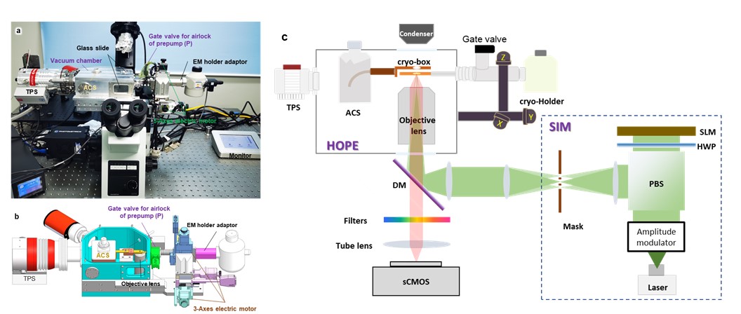
Figure 1. Design and principle of the HOPE-SIM system. (a) A real photograph of an Olympus IX73 inverted microscope with the mounted HOPE-SIM stage. TPS, turbo pump system; ACS, anti-contamination system. (b) Section view of the design of the HOPE-SIM stage. Each part of the system is labeled and described. (c) Schematic overview of the HOPE-SIM system design in its operational mode.
We demonstrated that our HOPE-SIM system can achieve cryo-SIM imaging with a resolution of ~200 nm in the lateral direction and ~500 nm in the z direction. These results are better than the conventional wide-field cryo-FM and deconvolution modes. We verified the precision of the correlation between cryo-SIM and cryo-FIB as 110 nm, which is good to perform accurate site-specific cryo-FIB fabrication of cryo-lamella with a thickness of ~200 nm. We applied our HOPE-SIM-based cryo-CLEM workflow to successfully target MitoTracker-stained mitochondria in HeLa cells, visualize mCherry-tagged MHV-68 virions under tegumentation in infected BHK-21 cells, and obtain a tomogram of the human centrioles in HeLa cells. The high success rate of targeting the human centrioles suggests the robustness and accuracy of our cryo-CLEM workflow.
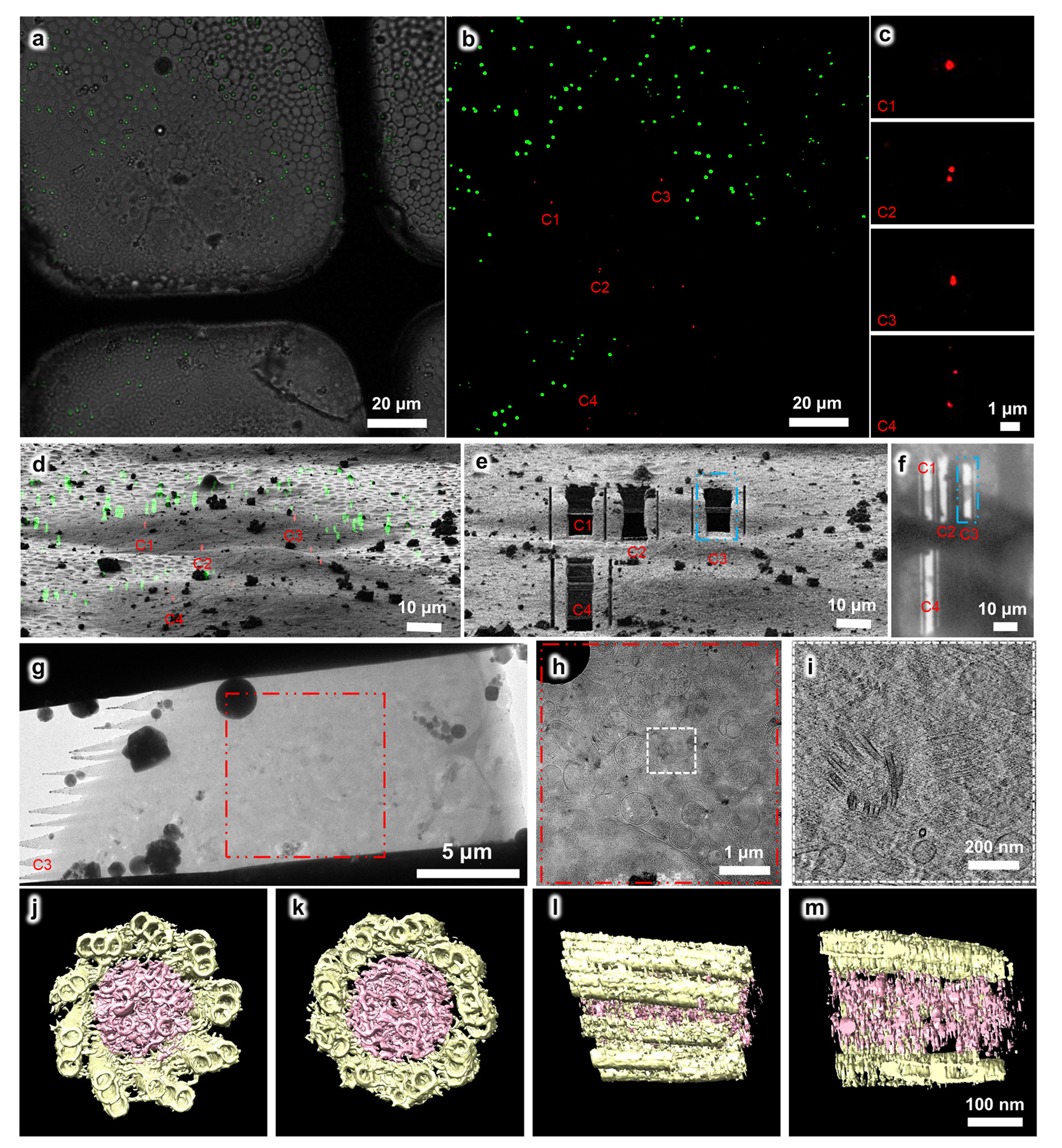 Figure 2. Using the HOPE-SIM-based cryo-CLEM workflow to capture the centrosomes in HeLa cells. (a) Bright field image of the target square is merged with the z projection of HOPE-SIM fluorescent image in (b), where the microspheres (green) are well spread, and the fluorescence-labeled centrosomes (red) are well resolved. Four sets (C1-4) of centrosomes are selected C1-4 for subsequent cryo-FIB fabrication. (c) Zoomed-in view of the four sets of centrosomes in (b). (d) 3D correlation between HOPE-SIM and cryo-FIB images to localize the positions of the selected centrosomes. (e) Cryo-FIB image after fabrication at the positions of C1-4 in (d). The cryo-lamella C3 indicated by the blue dashed rectangle is subjected to cryo-ET data collection. (f) Low magnification (155×) cryo-EM image of the cryo-lamellae in (e). (g) Cryo-EM micrograph of the C3 cryo-lamella with the magnification of 4,300×. (h) Cryo-EM micrograph (8,700×) of the C3 cryo-lamella at the region of the red square in (g). The target region marked by the white square is subjected for cryo-ET data collection and reconstruction. (i) One slice of the tomogram (53,000×) of the target region, showing the target centrioles with one in the top view and another in the side view. (j-m) 3D in situ structure of the centriole in HeLa cells with different views, (j) top, (k) bottom, (l) side and (m) cross. The triplet tubules are shown in yellow, and the internal scaffold structures are shown in pink.
Overall, our HOPE-SIM system-based cryo-CLEM workflow provides an efficient non-integrated solution to achieve accurate target cryo-FIB fabrication of cryo-lamella ready for site-specific cryo-ET study. Our HOPE-SIM system is versatile and can be adapted for various fluorescence and electron microscopes by utilizing proper stages, cryo-holders, and cartridges. In the future, besides further integration with our ELI-TriScope system10 in one direction, we will also upgrade our HOPE-SIM system using the progressive deep-learning super resolution strategy to achieve a higher resolution and update the 3D-View software to realize fully automatic image correlation, making a more efficient and accurate non-integrated solution of site-specific cryo-FIB milling.
1.Schröder, R. R. Advances in electron microscopy: A qualitative view of instrumentation development for macromolecular imaging and tomography. Archives of Biochemistry and Biophysics 581, 25-38 (2015).
2.Marko, M., Hsieh, C., Schalek, R., Frank, J. & Mannella, C. Focused-ion-beam thinning of frozen-hydrated biological specimens for cryo-electron microscopy. Nature Methods 4, 215-217 (2007).
3.Zhang, J., Ji, G., Huang, X., Xu, W. & Sun, F. An improved cryo-FIB method for fabrication of frozen hydrated lamella. Journal of structural biology 194, 218-223 (2016).
4.Hampton, C. M. et al. Correlated fluorescence microscopy and cryo-electron tomography of virus-infected or transfected mammalian cells. Nature protocols 12, 150-167 (2017).
5.De Boer, P., Hoogenboom, J. P. & Giepmans, B. N. G. Correlated light and electron microscopy: ultrastructure lights up! Nature Methods 12, 503 (2015).
6.Wu, G. H. et al. Multi-scale 3D Cryo-Correlative Microscopy for Vitrified Cells. Structure 28, 1231-1237.e1233 (2020).
7.Hoffman, D. P. et al. Correlative three-dimensional super-resolution and block-face electron microscopy of whole vitreously frozen cells. Science 367 (2020).
8.Klein, S., Wachsmuth-Melm, M., Winter, S. L., Kolovou, A. & Chlanda, P. Cryo-correlative light and electron microscopy workflow for cryo-focused ion beam milled adherent cells. Methods in Cell Biology 162, 273-302 (2021).
9.Li, S. et al. High-vacuum optical platform for cryo-CLEM (HOPE): A new solution for non-integrated multiscale correlative light and electron microscopy. Journal of structural biology 201, 63-75 (2018).
10.Li, S. et al. ELI trifocal microscope: a precise system to prepare target cryo-lamellae for in situ cryo-ET study. Nature Methods 20(2):276-283(2023).
Follow the Topic
-
Communications Biology

An open access journal from Nature Portfolio publishing high-quality research, reviews and commentary in all areas of the biological sciences, representing significant advances and bringing new biological insight to a specialized area of research.
Related Collections
With Collections, you can get published faster and increase your visibility.
Signalling Pathways of Innate Immunity
Publishing Model: Hybrid
Deadline: Feb 28, 2026
Forces in Cell Biology
Publishing Model: Open Access
Deadline: Apr 30, 2026


Please sign in or register for FREE
If you are a registered user on Research Communities by Springer Nature, please sign in